For a while now I wanted to start using Raspberry Pi computers. I finally got one and, as many people do, started to thinking about housing this credit card sized computer. After a few months I had a fully functional Raspberry laptop in a stylish wooden case.


Since I do not need such a stylish laptop I will sell it. If you are interested: buy it here.
While many people liked the Raspberry laptop, there were quite a few that would prefer their own, more powerful, computers housed in a similar case. I thus made a few cases inspired by this project (images here or buy them here).
I will probably buy another Raspberry Pi for some or other project but house it in a simple cardboard box.
—
How I made it:
As with many of the things I make, I have a idea of the final product in my head (or a extremely simple drawing with a few measurements – see below) but definitely not all the steps. During the building process I needed to make many changes and improvised a lot. In addition, many of the steps happened in parallel which helps to bring everything together at the end. The making of this laptop is shown in the series of videos and photos below. You can also click HERE to watch the full playlist on YouTube – but come back to read the interesting anecdotes and see more awesome pictures.
The making of this laptop started with a very simple drawing.

The main idea was to have all the components in one part of the case. The other side would open to show the screen and keyboard and also provide access to the compartment that house some cables and a mouse. The main problem was thus how to fit everything into the case. I also wanted a “nice box” and might have spent a bit too much time on the details. The 2 videos below show the making of the outer and inner part of the laptop case.
The top part quite thick relative to the bottom part, and if the laptop was not unique enough this would be a feature that would distinguish it from most other laptops.

Initial fitting of the screen and the large battery.

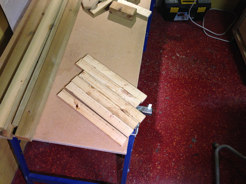
Most of the wooden components – pre assembly

Test fit of the internal components

Assembly of the outer case almost done
I liked the striped plywood sides and wanted to keep the same style with the latches. These parts took quite a bit of time to make (I could have used store bought latches and saved many hours). I am however happy with the design. Below is a video focusing only on how I made the latches.
I did mention that I wanted a “nice box” and a lot of small details were added to the case. Below is a video that show how these were made:
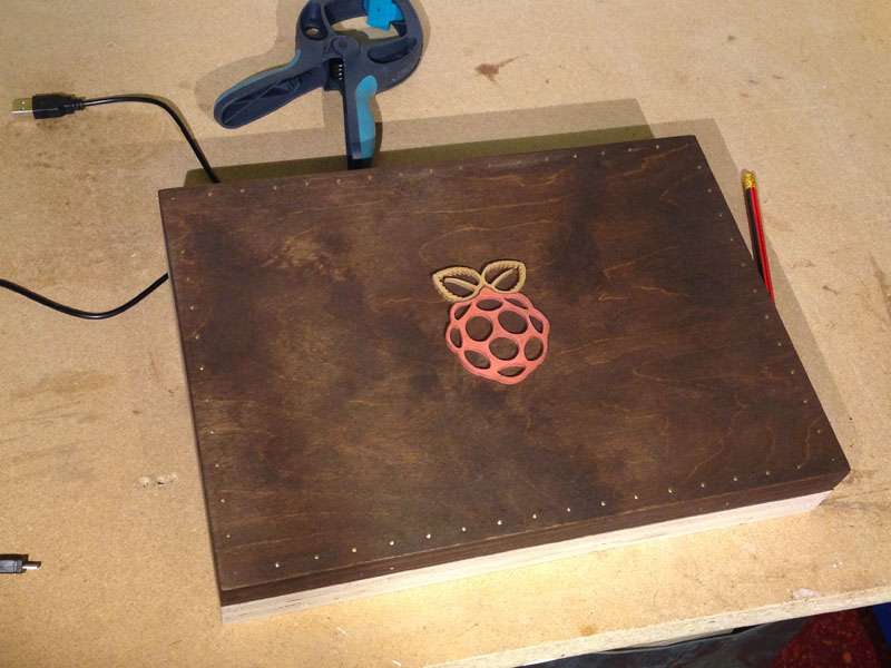
Logo added to the case – before lacquer
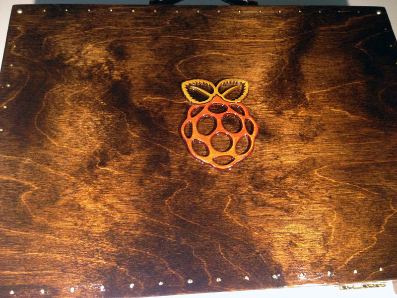
After lacquering
The whole case was finished with several coats of polyurethane lacquer.

Small parts were made and kept here until assembly

Closeup of the red feet
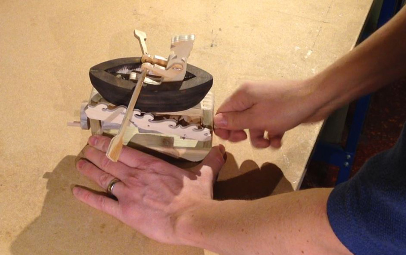
In addition to the feet I added a copper chain to stop the case from opening too far. I made a simple spool to retract the chain when opening and closing the case (can bee seen in part 2 of the video series). Below is a closeup of this device.
Simple chain retractor
The last part was the final assembly. At this stage everything was fitted several times and I mainly had to screw all the electronics in place one last time.

Everything in place

Finished Laptop Case

—
Problems and improvements.
After the laptop was completed I found that it was a bit tricky to link the earphones every time. I thus added a small mobile speaker to the inside of the case (there was just enough room next to the Raspberry Pi). It might however have been easier to just add an extension cable that is accessible from the front compartment to plug the earphones into – but it is nice to have some internal sound.
When opening the laptop the feet and chain stop it from opening too far. The feet are however just too short and the bottom lid lifts slightly before it stops (longer feet would however look weird). This is not problematic as such but it almost seem that it will fall over when opening – but never does. I fixed this problem in the laptop cases that work on the same principle (here).
I think a smaller portable battery would be sufficient. I never run out of power and rarely need to recharge. This would allow the case to be quite a bit smaller.
I find that the mouse and keyboard has a bit of a lag with the Raspberry. I am not sure if this is just because I am used to directly connected peripherals and fast computers or if I am just a bit impatient.
I will probable not make another Raspberry Pi laptop. The problems are also small enough to not change the current look of the laptop.
Specifications
More on the specifications of the Raspberry Pi 3 can be read here.
The screen is the official Raspberry Pi 7″ touch screen more information here.
The laptop will be sold with a Linocell Bluetooth keyboard (more information here) and a Plexgear wireless mouse (more information here). The mouse fits snugly in the front compartment.
It is powered by a EnerPlex battery pack inside the case (more information here). The battery is a Lithium Ion with a capacity of 10400mAh. The battery can be charged via a normal 5V USB (a cable is stored inside the back of the case).
A Streetz speaker is also included and sits neatly inside the back of the case ( more information here).
The speaker and keyboard can be charged with the internal battery and an a micro USB cable is also provided (and kept in the front compartment of the case).
Note, the links to the peripherals are from the companies where each item was purchased.
The size of the laptop is 33 x 26 x 7.5 cm
The laptop weighs 2.8 kg (all peripherals included).
—
As mentioned, I made some laptop cases inspired by this project. These house 13″ MacBook Pro laptops. Below are some images of these. More about them here or to see them in the shop here.


Robroy
—